Electric Fence Management (Geofence)
The Electric Fence module allows you to integrate floor plan maps, draw virtual security perimeters (Geofences), and link them to the physical signal ports of the controller hardware to detect intrusions.
1. Adding a Map to the List
To begin the setup, you need to load a floor plan into the workspace:
- Right-click on an empty area in the list panel (Treeview) on the left side.
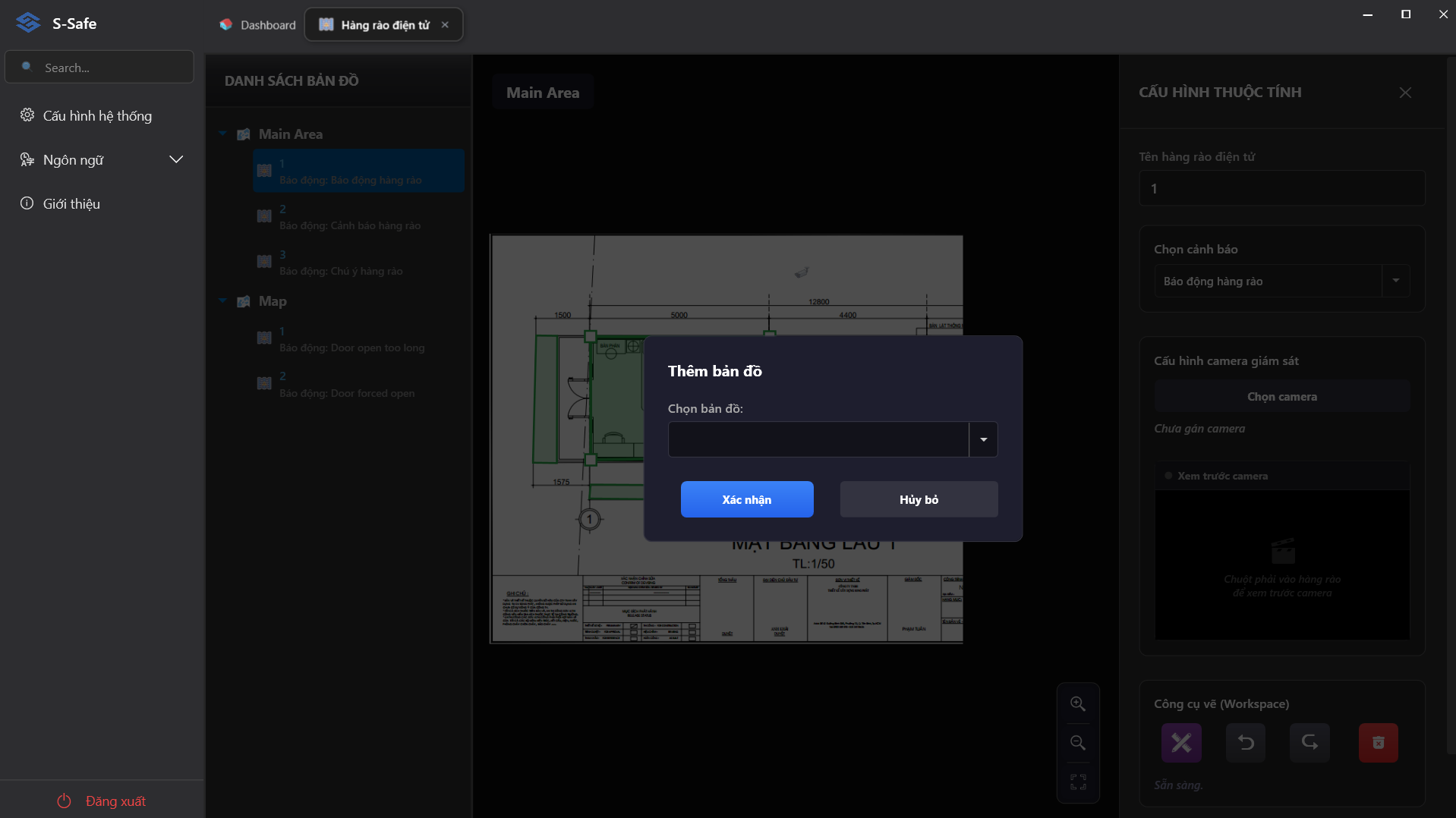
- Select Add Map. The Add Map dialog will appear:
- Area: Select the Zone/Area already created in the system to link with this map (e.g., Main Area Test).
- Click Save to confirm.
2. Working with the Treeview and Drawing Fence Zones
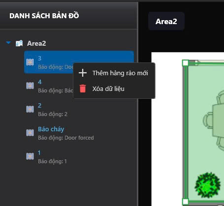
After the map is added to the list, right-click directly on the map name (e.g., Main Area Test) to open the context menu:
- Add Fence: Allows you to create a new geofence zone under this map.
- Delete: Remove the map from the list.
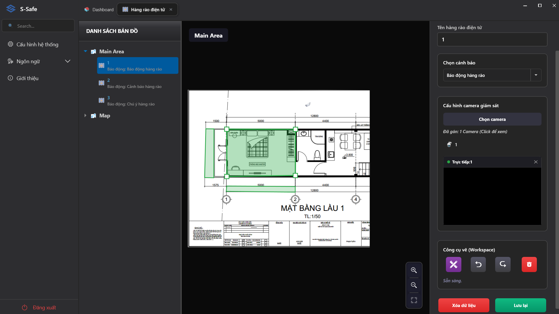
When you choose to draw a fence, the central map canvas will allow you to click points to form a closed polygon (a light blue shaded area with a red border) enclosing the zone to be protected.
3. Configuring Hardware for a Fence (Add Fence)
When you create a new geofence, the Add Fence dialog will require you to configure the hardware link parameters:
- Name: The identifying name for the fence (e.g., F12, Parking Lot, Warehouse).
- Alert: Select the appropriate alert scenario/level pre-configured in the system (e.g., Fence Alarm, Fence Warning, Fence Notice).
- Surveillance camera configuration:
- Click the Select Camera button to open the Assign Camera to Fence dialog box:
- Select priority camera (displayed upon alarm): Choose a primary camera from the drop-down list. This camera will automatically switch to a priority Liveview display on the screen whenever an alarm event occurs at the fence.
- Select secondary cameras (for supplementary viewing): Check the boxes next to additional cameras in the list to monitor multiple angles around the fence area.
- Click Confirm to apply the settings or Cancel to close the dialog box.
- Displays the list and count of assigned cameras (e.g., Assigned: 1 Camera).
- View the live video feed (Liveview) of the selected camera directly within the fence configuration interface.
- Click the Select Camera button to open the Assign Camera to Fence dialog box:
- Drawing Tools (Workspace):
- Drawing Tool: Click the drawing icon to outline the fence area directly on the map.
- Undo / Redo: Click the arrow icons to cancel or re-apply the previous drawing action.
- Delete Drawn Area: Click the red trash can icon to remove the area just drawn on the map.
Once configuration is complete, click Save (green) to save the settings, or click Delete Data (red) to discard them.